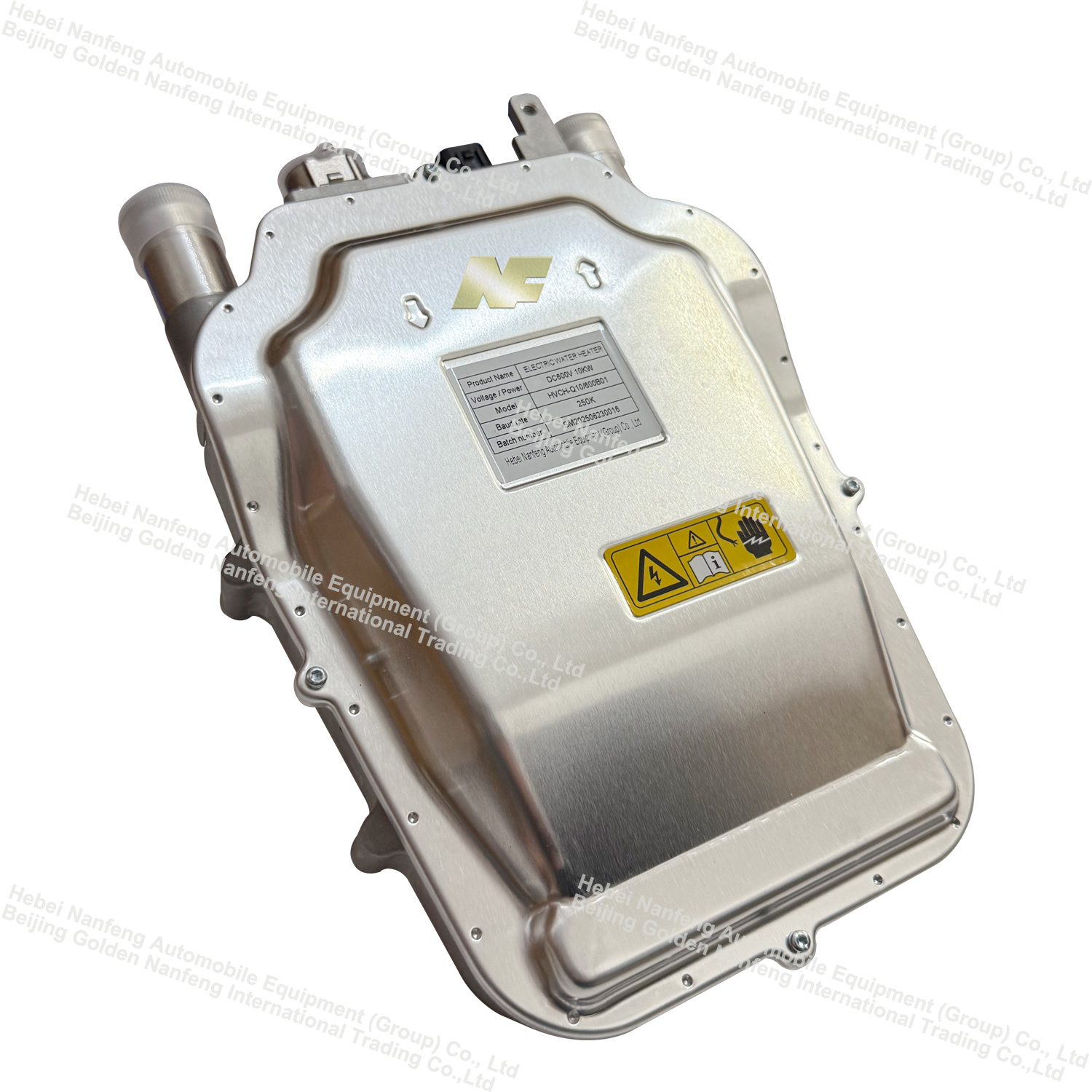
Structure of PTC coolant heater


1. PTC heating core
This is the "heart" of the entire heater and the core of energy conversion.
(1) PTC ceramic chip: usually made of semiconductor ceramic materials such as barium titanate, with a positive temperature coefficient effect. That is, when the temperature is low, the resistance is small, the power is large, and the heat is fast; as the temperature rises, its resistance will increase sharply and the power will automatically decrease, thus playing the role of automatic constant temperature and safety protection against overheating. This is a huge advantage of PTC over traditional heating wires.
(2) Electrode sheet: usually made of copper or aluminum, attached to both sides of the PTC ceramic chip, used to connect high-voltage current.
(3) Thermal insulation layer: multiple PTC chips and electrode sheets are assembled into a stacked structure, and the chips are isolated with insulating but thermally conductive ceramic sheets or alumina sheets to ensure electrical safety while efficiently conducting heat.
2. Water jacket
This is a key component that is in direct contact with the coolant and performs heat exchange.
(1) Material: usually aluminum alloy, because aluminum has good thermal conductivity, light weight, and is easy to process.
(2) Structure: The internal design has complex flow channels. The PTC heating core is tightly inserted or pressed between these flow channels. When the coolant flows through these tortuous flow channels, it can maximize contact with the heating core, absorb heat, and improve heat exchange efficiency.
(3) Sealing: There are inlets and outlets, and the watertightness and pressure bearing capacity of the connection with the external pipe are ensured by sealing rings (such as O-rings) or brazing processes to prevent coolant leakage.

3. High-voltage electrical interface and control system
(1) High-voltage terminal: used to connect the high-voltage battery (usually 300V-800V DC) of new energy vehicles to provide energy for PTC. The interface design has anti-touch and anti-short circuit protection.
2) Control module: usually part of the heater assembly or communicates with the vehicle controller (VCU).
① Receiving signals: Receive heating requests and temperature setting signals from the air conditioning panel or battery management system (BMS).
② Power Regulation: The PTC heater's heating power is precisely adjusted by switching on and off relays or IGBTs, or by PWM (pulse width modulation) control, enabling on-demand heating and energy conservation.
③ Fault Diagnosis: The system features protection for overcurrent, overtemperature, water shortage (flow sensor), and short circuit. Upon detecting an abnormality, it immediately shuts off the power supply and reports a fault code.
4. Housing and Mounting Bracket
① Housing: Typically made of engineering plastics (such as PP, PA+GF) or metal, it encapsulates and protects all core components within, providing electrical insulation, waterproofing, dustproofing (typically requiring an IP67 rating), and structural support.
② Mounting Bracket: Secures the entire PTC heater assembly to the designated location on the vehicle body.
5. Sensor
Water Temperature Sensor (NTC): Installed at the inlet and outlet of the water jacket, it monitors the coolant temperature in real time and provides feedback to the control module for precise temperature control and overtemperature protection.
NF Group Launches High-Power PTC For EV Buses
Anxious about the range of new energy vehicles?
Related Article